What is FEA?
Finite element analysis (FEA) is a numerical method for analyzing the behavior of structures under loads and boundary conditions. It is a key tool in the design of plastic parts, as it allows engineers to predict the strength, stiffness, and deformation of a part under different loading conditions.
In FEA, a structure is represented as a mesh of small, interconnected elements. Each element is a simplified representation of a small portion of the structure, and the behavior of the element is described by a set of equations. By solving these equations for each element, and then combining the solutions for all the elements, the behavior of the entire structure can be predicted.
One of the primary benefits of FEA is that it allows engineers to analyze a wide range of loading conditions and boundary conditions, including static, dynamic, and thermal loads. This is particularly useful in the design of plastic parts.
Using FEA in the Design of Plastic Parts
To use finite element analysis (FEA) in the design of a plastic part, follow these steps:
Define the problem: Begin by clearly defining the problem you are trying to solve. This may involve specifying the type of load that the part will be subjected to (e.g. static, dynamic, thermal), the boundary conditions (e.g. fixed, pinned, sliding), and the performance requirements for the part (e.g. strength, stiffness, deformation).
Develop a model: Next, create a computer model of the plastic part using a finite element software program. This may involve importing a CAD model of the part into the software, or creating a 3D model from scratch using geometric shapes and meshing tools.
Choose a material model: Select a material model that accurately describes the behavior of the plastic material being used. This may involve selecting a pre-defined material model from a library, or developing a custom material model based on test data.
Apply loads and boundary conditions: Specify the loads and boundary conditions that the part will be subjected to in the FEA model. This may involve applying forces, moments, or temperature changes to specific locations on the part, or constraining the motion of certain nodes in the mesh.
Solve the model: Run the FEA analysis to solve for the behavior of the plastic part under the specified loads and boundary conditions. This will typically involve solving a system of equations for each element in the mesh, and then combining the solutions to predict the behavior of the entire structure.
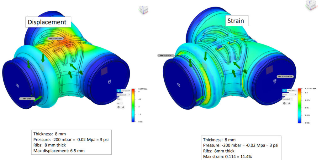
Review the results: Review the results of the FEA analysis, including the predicted stresses, strains, and deformations in the plastic part. These results can be used to evaluate the performance of the part and identify areas of the design that may need to be modified.
Optimize the design: If necessary, modify the design of the plastic part to improve its performance or reduce the amount of material required. This may involve redistributing loads more evenly, increasing the thickness of certain areas of the part, or altering the shape of the part to reduce stress concentrations.
Validate the results: Validate the results of the FEA analysis by comparing them to experimental data obtained from physical tests. This will help to ensure that the FEA results are reliable and can be used to make informed design decisions.
By following these steps, engineers can use finite element analysis to analyze the behavior of plastic parts under a wide range of loading and boundary conditions, and optimize the design of the part to improve its performance and reduce the amount of material required. Contact us at Master Plastics for assistance in FEA & part design.